The TBDP©/VBDP© analyzes the specified design of the skeg,

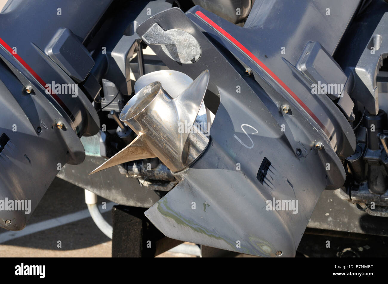
All of theseĬonstituents and fluid phases are exposed to interaction with the lower Water vapour (cavitation), air and exhaust gases. (see below) that determine the overall drag of the lower unit.įluid flow field around the lower unit components exists in all of water, There are many different designs of outboard lower units in use today every boat will have the lower unit set up with respect to the hull differently and there are several contributing drag components The Appendage drag of motor or outdrive lower unit is difficult to calculate in a simple manner. This performance is different for each design, each setup arrangement andĭrag contributors are different at each operating velocity. TBDP © /VBDP © Drive Unit Drag Analysis calculateĭrag and coefficients for ANY drive design configuration throughout the entire hull operating velocity rangeĪR® has developed complex algorithms that calculate hydrodynamic drag of the outboard lower unit or I/O outdrive design & configuration. When lower units are located in close proximity (comparison of lower unit Torpedo design of 3"įigure 6 - Lower Unit Drag vs Velocity graphic outputįigure 6 - TBDP/VBDP input screen for Lower Unit Designįigure 7 - Multi-engine interference drag increases (comparison of lower unit depth of -3" (below) waterįigure 5 - Torpedo diameter affects drag and performance

Inlet holes and ventilation from exhaust gas exit behind the propeller hubįigure 4 - Lower Unit height affects drag and performance Ventilation patterns for gearcase geometry shows cavitation behind water Figure 1 - Lower Unit Drag design & dimensional inputsįigure 2 - Lower Unit Drag coefficient vs Velocity graphic output


 0 kommentar(er)
